Return loss test method
Return loss test method
1. What is return loss?
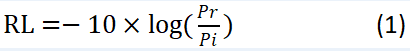
The return loss (RL) mentioned in this article is the ratio of the power incident or entering the product under test (Pi) to the total power reflected by the product (Pr), expressed in decibels:
2. Source of return loss
reflection
Reflection is caused by light passing from one medium into another medium with a different refractive index. The Fresnel phenomenon describes this reflection, so it is often called Fresnel reflection. For optical devices, reflections are caused by tiny particles at the optical coupling interface, caused by dirty contamination. and reflections from fiber optic cracks.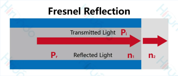
Figure 1. Fresnel reflection
scattering
When the light beam propagates forward in the optical fiber, it will scatter when encountering discontinuities in the optical fiber. The discontinuities may be caused by impurities in the fiber material, tiny air gaps, or even mechanical stretching. There are many types of scattering, the most common of which is Rayleigh scattering, whose intensity is inversely proportional to the fourth power of the wavelength of light. The main difference between Rayleigh scattering and Fresnel reflection is that Rayleigh scattering exists along the entire light path.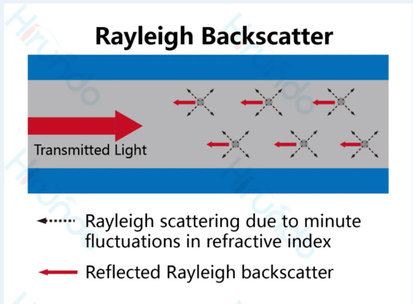
Figure 2. Rayleigh scattering
3. Return loss measurement method
International Electrotechnical Commission: Four return loss measurement methods are introduced (IEC-61300-3-6):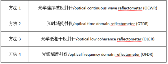
Among them, two of our most commonly used methods are the OCWR method and the OTDR method.
OCWR method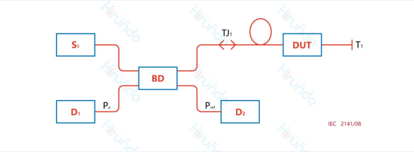
Figure 3. Measurement settings for return loss (OCWR method)
The OCWR method is the closest to the theoretical definition of return loss given by formula (1). It directly measures incident power and reflected power. Unaffected by instrument data processing, it gives absolute measurements rather than relative to a reference reflection (Technology A).
The following is a measurement guide
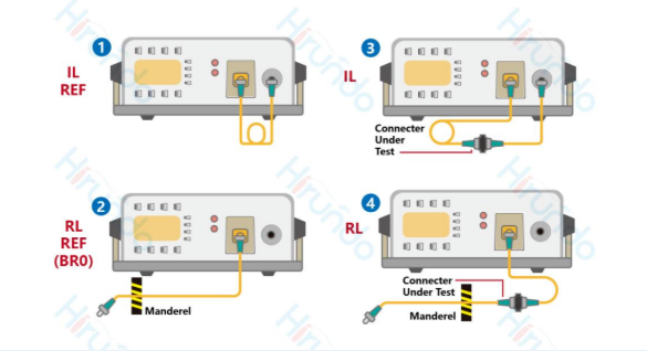
Figure 4. OCWR method
Figure 4: In order to accurately measure the return loss of the DUT, the OCWR method requires manual winding before and after connecting the DUT. This method requires the light to be terminated. The end point determines the length or light path of RL measurement, as shown in Figure 5: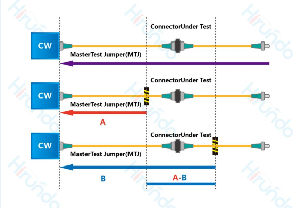
Figure 5. The end of light is key to the OCWR measurement method
The first mandrel, BR0, and the second mandrel determine the measurement area, and BR0 is used as a reference to eliminate the influence of measurement introduction fibers on the measurement results.
This method has some limitations: it cannot spatially resolve two different reflections on the line, its dynamic range is limited by the characteristics of the branch device and the ability to suppress reflections beyond the DUT, and typically the minimum RL that can be measured by the OCWR method The limit value is 70 dB.
OTDR method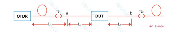
Figure 6. Measurement settings for return loss (OTDR method)
OTDR method: this method allows the use of OTDR instruments to measure RL from reflection points on the optical line with a spatial resolution in the meter range and a dynamic range of more than 75 dB (depending on the pulse width).
The following is a measurement guide: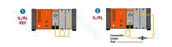
Figure 7. OTDR method Measurement diagram
The OTDR method does not require winding, and the basic setup is very simple, requiring only two steps, as shown in Figure 7. Defining the area for RL measurement is the key to OTDR measurement.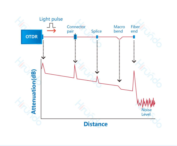
Figure 8. OTDR tracking example, mapping loss versus distance
A significant advantage of the OTDR method is that it can distinguish between Rayleigh scattering and Fresnel reflection, allowing users to choose to measure the RL of a certain joint, and can remove the influence of the test fiber introduction, so the measurement range can be increased from 70 dB to 80 dB.
4. Choice of measurement method
Since these methods have different characteristics and application fields, the choice of measurement method depends on the type of DUT.
For components with an RL of 55 dB, refer to the OCWR method;
For components with RL > 55 dB, refer to the OTDR method.
Before discussing any RL test results, it must be emphasized that proper inspection and cleaning are prerequisites for obtaining accurate test results, and connection issues are the reason why we get abnormal results most of the time. RL can only be accurately measured with proper connections, and the RL value will be affected by small changes in the connection surface each time a connection is made.