Transceiver | Small size with big effect
Transceiver | Small size with big effect
Although the optical module is small in size, its role in the data center cannot be ignored. Without it, no data center will be able to operate;
Especially today, as data centers have higher and higher bandwidth requirements, optical modules have even restricted the development of data centers to a certain extent.
What is a transceiver?
The transceiver (optical module) is composed of optoelectronic devices, functional circuits, optical interfaces, etc.
The optoelectronic devices include two parts: transmitting and receiving.
The function of the transceiver is to convert the electrical signal into an optical signal at the sending end.
and then convert the optical signal into an electrical signal at the receiving end after transmission through the optical fiber.
How Transceivers Work
The transceiver works at the physical layer of the OSI model and is one of the core devices in the optical fiber communication system.
it is mainly composed of optoelectronic devices (optical transmitters and optical receivers), functional circuits, and optical interfaces.
The main function is to realize the photoelectric conversion and electro-optical conversion functions in optical fiber communication;
The working principle of the transceiver is shown in the figure.
The sending interface inputs an electrical signal with a certain code rate, and after being processed by the internal driver chip,
The modulated optical signal of the corresponding rate is emitted by driving the semiconductor laser (LD) or light-emitting diode (LED).
After transmission through the optical fiber, the receiving interface converts the optical signal into an electrical signal by a photodetector diode.
and outputs an electrical signal with a corresponding code rate after passing through a preamplifier.
The appearance and structure of the transceiver
There are various types of transceivers, and their appearance structures are also different.
but their basic structure includes the following parts:
as shown in the figure: The appearance structure of the transceiver
Transceiver Key Performance Indicators (How to measure the performance index of the transceiver?)
Transceiver sender
1/
The average transmitted optical power refers to the optical power output by the light source
at the transmitting end of the transceiver under normal working conditions,
which can be understood as the intensity of light;
The transmitted optical power is related to the proportion of "1."
in the transmitted data signal, the more "1," the greater the optical power;
When the transmitter sends a pseudo-random sequence signal, "1" and "0" roughly account for half each.
At this time, the power obtained by the test is the average transmitted optical power, and the unit is W or mW or dBm.
Among them, W or mW is a linear unit, and dBm is a logarithmic unit.
In communication, we usually use dBm to represent optical power.
2/
The extinction ratio refers to the minimum value of the ratio of the average optical power
of the laser when emitting all "1" codes to
the average optical power emitted when all "0" codes are emitted under full modulation conditions, and the unit is dB;
When we convert an electrical signal into an optical signal,
the laser in the transmitting part of the transceiver converts it
into an optical signal according to the code rate of the input electrical signal;
The average optical power when all "1" codes represent the average power of the laser emitting light,
the average optical power when all "0" codes
represent the average power when the laser does not emit light,
and the extinction ratio represents the ability to distinguish between 0 and 1 signals.
Therefore, the extinction ratio can be regarded as a measure of the operating efficiency of a laser.
Typical minimum values for extinction ratios range from 8.2 dB to 10 dB.
3/
In the emission spectrum, the wavelength corresponds to the midpoint of the line segment connecting the 50% maximum amplitude values.
Different types of lasers or two lasers of the same type will have differences in central wavelength due to process, production, and other reasons.
Even the same laser may have different central wavelengths under different conditions. Generally,
Manufacturers of optical devices and optical modules provide users with a parameter, that is, the central wavelength (such as 850 nm).
This parameter will generally be a range. At present, there are mainly three central wavelengths of commonly used optical modules: 850 nm band,
1310 nm band and 1550 nm band. Why is it defined in these three bands?
This is related to the loss of the optical fiber transmission medium of the optical signal. Through continuous research and experiments,
It is found that the fiber loss usually decreases with the length of the wavelength; the loss at 850 nm is less, and the loss at 900 ~ 1300 nm becomes higher.
And 1310 nm becomes lower again, 1550 nm has the lowest loss, and the loss above 1650 nm tends to increase.
So 850 nm is the so-called short wavelength window, and 1310 nm and 1550 nm are long wavelength windows.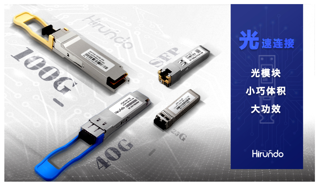
transceiver receiver
1/
Saturation optical power refers to the maximum input average optical power that the receiver components can receive under
a certain bit error rate (BER=10-12) condition of the transceiver; the unit is dBm.
It should be noted that the photodetector will exhibit the photocurrent saturation phenomenon under strong light irradiation.
When this phenomenon occurs, the detector needs a certain period of time to recover. At this time, the receiving sensitivity decreases,
and the received signal may be misjudged. cause code errors.
To put it simply, if the input optical power exceeds this overload optical power, it may cause damage to the equipment.
During use and operation, try to avoid strong light exposure to prevent exceeding the overload optical power.
2/
Receiving sensitivity refers to the minimum average input optical power that the receiving end
components can receive under the condition of certain bit error rate (BER=10-12) of the optical module;
If the transmitted optical power refers to the light intensity at the sending end, then the receiving sensitivity refers to the light intensity that the transceiver can detect.
The unit is dBm. In general, the higher the rate, the worse the receiving sensitivity; that is, the greater the minimum received optical power,
the higher the requirements for the receiving-end components of the transceiver.
3/
Received optical power refers to the average optical power range that the receiver components can receive under a certain bit error rate (BER=10-12) condition. The unit is dBm;
The upper limit of the received optical power is the overload optical power, and the lower limit is the maximum value of the receiving sensitivity.
Interface rate: the maximum electrical signal rate that an optical device can carry without error.
The Ethernet standard stipulates 125 Mbit/s, 1.25 Gbit/s, 10.3125 Gbit/s, and 41.25 Gbit/s.
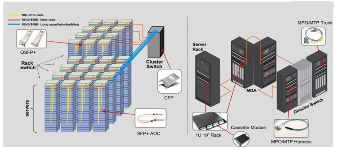
Hirundo transceiver products can provide you with more choices
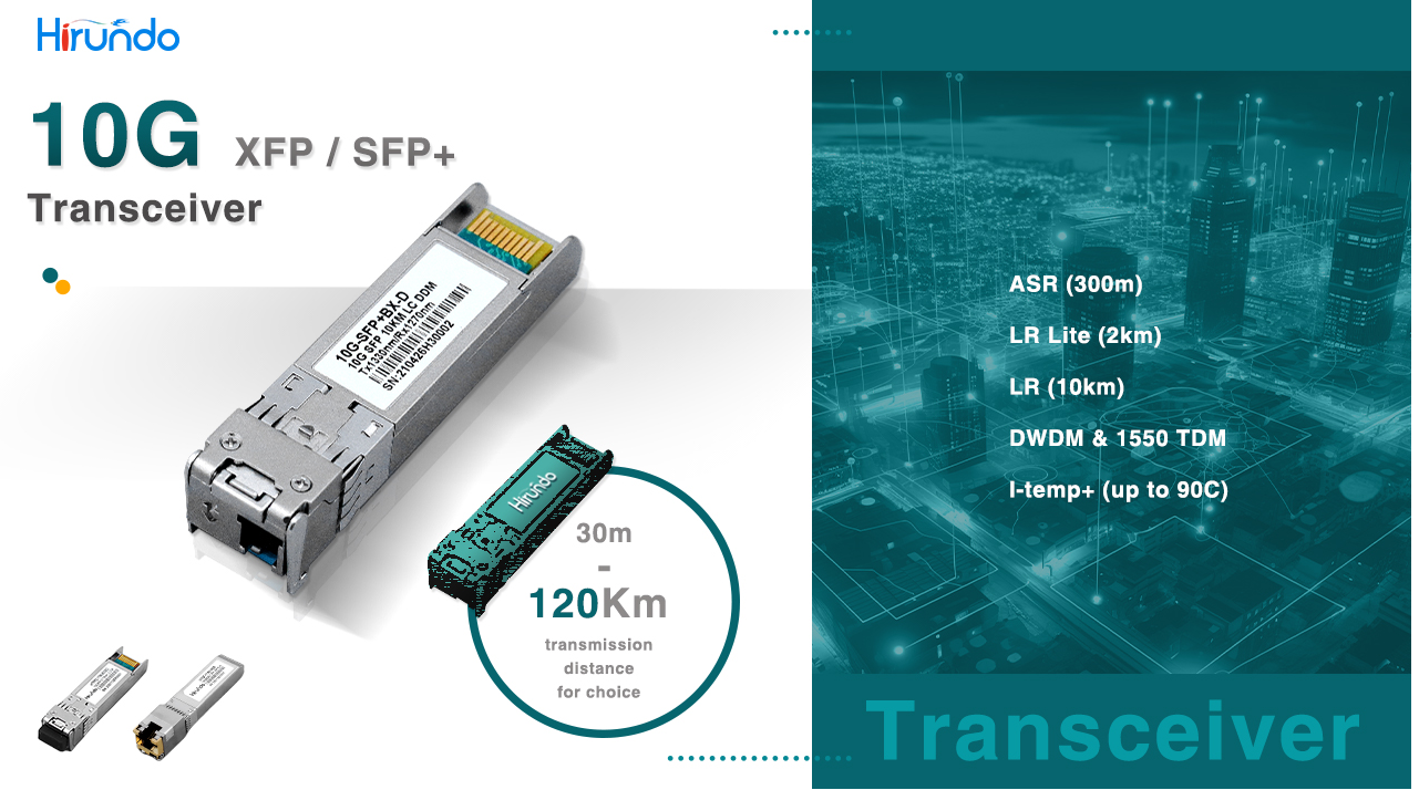
1、Types of 10G Transceivers
A 10G transceiver is a fiber optic module for a transmission rate of 10 Gbps.
10G transceivers can transmit data through optical fiber media to achieve high bandwidth and long-distance data transmission.
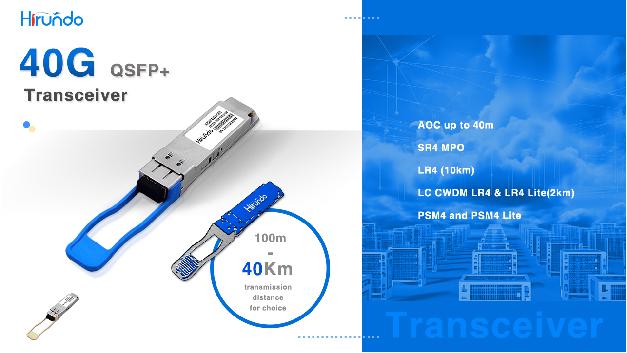
2、Types of 40G Transceivers
"40G transceiver" refers to a transceiver with a transmission rate of 40 Gbps.
QSFP+ and CFP are its main packaging forms, and 40G QSFP+ transceiver is one of the more widely used ones.
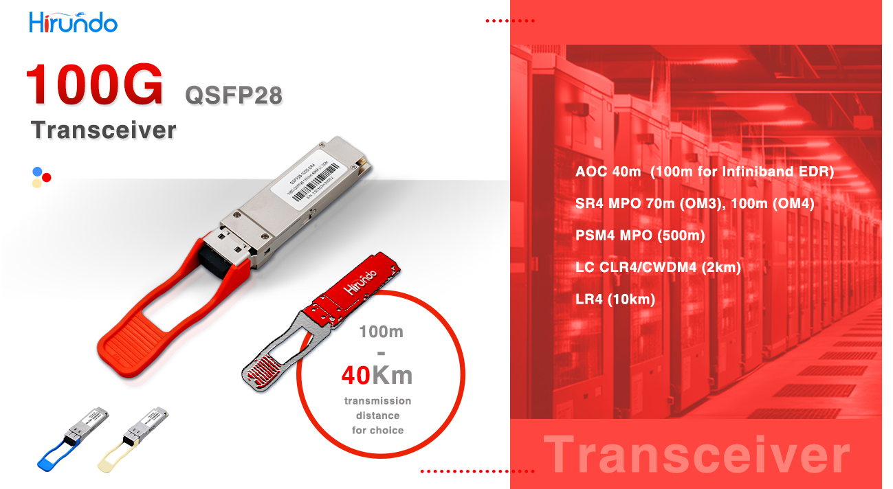
3、Types of 100G Transceivers
A 100G transceiver is a fiber optic module for a transmission rate of 100 Gbps.
It is a key component for achieving ultra-high bandwidth and high-speed data transmission.
According to different packaging methods, 100G transceivers mainly include CFP2, CFP4, and QSFP28.
The principle of 100G QSFP28 transceivers is similar to that of 40G QSFP+ transceivers.
and adopts 4-channel full-duplex mode for data transmission.
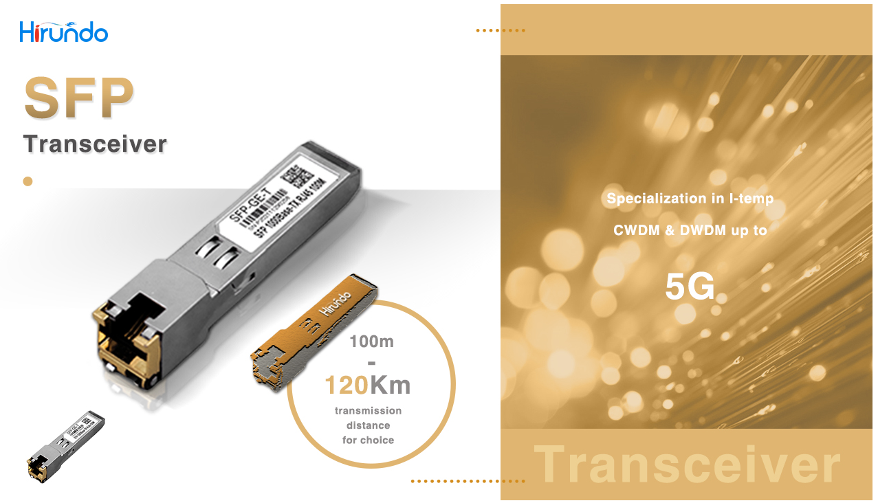
4、SFP
(Small Form-Factor Pluggable) The SFP transceiver is a hot-swappable optical module with a relatively small size and is suitable
for applications with a transmission rate lower than or equal to 1 Gbps;
It supports multiple fiber types, including multi-mode and single-mode fiber, and different transmission distance requirements.
The size of the SFP module is half that of the GBIC module, only the size of a thumb;
More than double the number of ports can be configured on the same panel;
other functions of the SFP module are basically the same as those of the GBIC.
and some switch manufacturers call the SFP module a miniaturized GBIC (MINI-GBIC).
The difference between SFP+ and SFP
1. The appearance and size of SFP and SFP+ are the same;
2. SFP protocol specification: IEEE802.3, SFF-8472;
SFP+ with XFP
1. Both SFP+ and XFP are 10G transceivers, and can communicate with other types of 10G modules.
2. Because of the smaller size, SFP+ integrates signal modulation functions, serial/deserializer, MAC, clock and data recovery (CDR),
And the electronic dispersion compensation (EDC) function is moved from the module to the motherboard card.
3. The protocol that XFP complies with: XFP MSA protocol.
4. Protocols complied with by SFP+: IEEE 802.3ae, SFF-8431, SFF-8432;