Multicore fiber (MCF)
Multicore fiber (MCF)
As 5th Generation mobile networks (5G) technology moves towards commercialization and the Internet of Things smart cities continue to develop,
The demand for optical communication capacity continues to increase.
In Single Mode Fiber (SMF) links, technical means such as time division multiplexing, wavelength division multiplexing, and polarization multiplexing can be used to expand system capacity.
However, with the growth of digital data services, the required bandwidth density The dramatic growth resulted in SMF links being unable to meet demand.
Spatial Division Multiplexing (SDM) based on multi-core fiber (Multi-Core Fiber, MCF) is one of the most effective methods to solve the capacity limitation of SMF links.
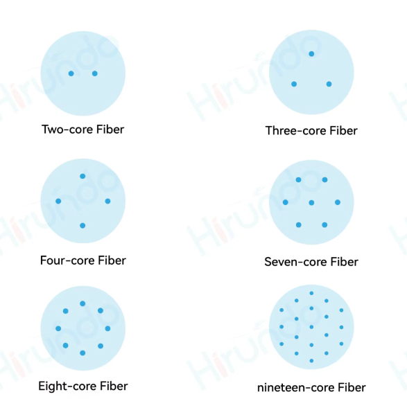
Common multicore fiber—Multicore fiber (MCF) has the following types:
Due to the different size and structure of optical fibers, in the actual application of MCF, a coupling element between MCF and single-core optical fiber is required.
This type of component is called a Fan-In/Fan-Out (FIFO) device.
The MCF FIFO device is an essential key device connecting the SMF bundle and MCF.
At present, the manufacturing methods of MCF FIFO devices mainly include four types: the fusion method, the fiber bundle method, the free space light method, and the three-dimensional integrated waveguide method.
1. Melting method
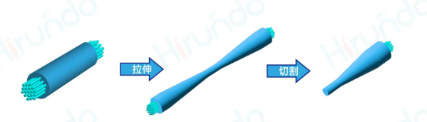
The fusion tapering method refers to bringing two (or more) optical fibers with the coating layer removed, melting them at high temperature, and stretching them to both sides at the same time.
Finally, a double cone structure is formed in the heating area. By controlling the torsion of the optical fibers, the angle or stretched length enables functions such as coupling or splitting of light.
The process of making FIFO using the fusion tapering method is relatively simple and requires less equipment.
However, in application scenarios with high index requirements,
The refractive index distribution of the optical fiber needs to be carefully designed, and the tapering process needs to be strictly controlled.
2. Fiber optic bundle method
Making MCFFIFO devices by preprocessing optical fiber bundles means first etching, customizing, or using other methods to make the outer diameter of multiple single-core optical fibers equal to the core spacing of MCF.
and then combining the multiple single-core optical fibers according to the proportion and structure.
Arrange, then fix and polish the end face, and finally fuse the optical fiber bundle with MCF or form a FIFO device through physical docking.
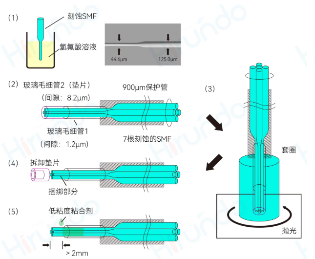
The key to the fiber bundle method is to process and arrange multiple single-core optical fibers, and the operation process is relatively delicate.
The cladding of single-core fiber can be etched or customized, and it needs to be consistent with the core spacing of MCF.
Therefore, the processing process needs to be strictly controlled, and the arrangement of single-core optical fibers also requires high-precision equipment.
Compared with the fused tapering method, the cost advantage of the fiber bundle method is not great; the insertion loss is relatively good, and the crosstalk is relatively low.
3. Free space light method
The free space light method refers to the use of bulk optical methods to make MCF FIFO devices.
that is, using bulk optical components such as lenses, prisms, and adjustment mounts to adjust and
Optimize the coupling between MCF and multiple single-core fibers to optimize the coupling efficiency.
and finally fix the optical path, forming an MCF FIFO device.
The advantage of using the free-space light method to fabricate MCFFIFO is that the connection between each core in the MCF and a single single-core fiber can be adjusted independently and is independent of polarization.
However, when the number of cores increases, the optical path becomes more complex, requiring higher accuracy and stability of the adjustment mount and optical components.
This method can be selected when the number of cores is small and polarization is required.
4. Three-dimensional integrated waveguide type
Waveguide-type MCFFIFO devices are devices that export light from each core in MCF to multiple single-core fibers through different waveguides on various platforms.
such as glass, polymer, planar optical waveguide, silicon-based, or silicon nitride.

Silicon-based optoelectronics has the advantages of compatibility with complementary metal oxide semiconductor processes, low cost, high integration, and high reliability.
It is the best solution to realize optoelectronics and microelectronics integration and optical interconnection.
Therefore, silicon-based optoelectronics has great potential. platform. When silicon-based devices are used in MCF optical transmission systems,
The connection between silicon-based optical devices and MCF can be easily achieved through silicon-based FIFO devices.
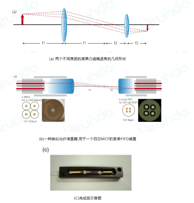
Based on the above main manufacturing methods of MCF FIFO devices, this article introduces a compact and low crosstalk XT FIFO component. Use commercially available fiber optic collimator assemblies.
The method is based on simple image segmentation using two microlens collimators with different focal lengths and can be easily implemented for most MCFs with square or hexagonal core arrangements.
4. How Core MCF FIFO works
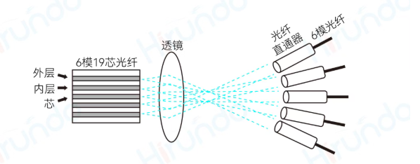
Figure (a) shows the basic geometry of image segmentation using two simple convex lenses.
In an imaging system, when an object is placed at the focus of the first convex lens, a true, inverted,
and a demagnified image can be formed at the focus behind the second convex lens.
The defocus rate is determined by the focal length ratio of the two lenses (f2/f1) and
can be used to convert the core pitch distance from the input SMF to the output MCF to implement a FIFO device.
This technique can be used on most MCFs with square or hexagonal center arrangements.