FBT coupler
FBT coupler
Basic principle of fused tapered coupler
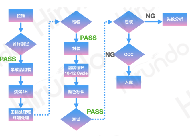
Figure 1. Fiber fusion tapering process
Hirundo's production process and equipment guarantee capabilities
The basic principle of the fused cone coupler
The fused cone coupler is composed of two parallel optical fibers. By twisting two optical fibers together, heating them to a molten state, and simultaneously slowly stretching the optical fibers, various Fused Biconical Taper devices (FBT) can be made. FBT devices are all-fiber type devices, featuring low loss and small size, and are widely used in optical communication systems.
During the manufacturing process, light waves are continuously input to the P0 port, and then the output power of each output port is monitored in real time. When the designed coupling ratio is reached, the fully automatic manufacturing process will stop stretching, and this process is called the melt cone drawing process.
Introduction to the Mode Coupling Fused Cone Coupler mode coupling
The most fundamental principle of FBT devices is the mode coupling theory. If multiple modes can be transmitted in a waveguide, when there are perturbations, such as changes in the waveguide diameter, energy exchange will occur between these modes, that is, coupling occurs between the modes. The coupling coefficient between modes is related to the difference in the propagation constants between them. The closer the propagation constants are, the greater the coupling coefficient will be.
Taper limit
The diameter of the optical fiber melting cone region gradually decreases. If the diameter changes too rapidly, higher-order modes will be excited, resulting in losses. The limitation on the taper corresponds to the external pulling speed during the cone-pulling process. During the manufacturing process, light waves are continuously input to the P0 port, and then the output power of each output port is monitored in real time. When the designed coupling ratio is reached, the fully automatic manufacturing process will stop stretching, and this process is called the melt cone drawing process.
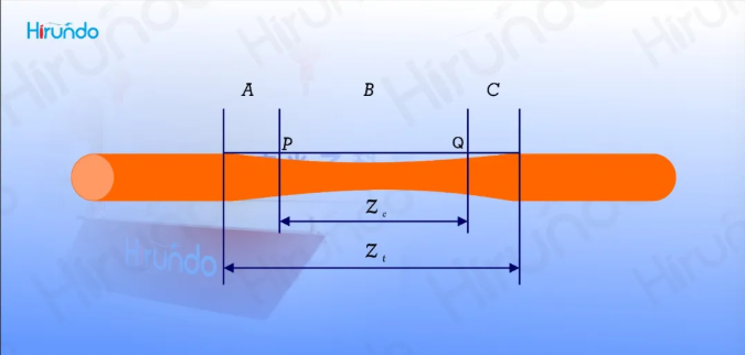
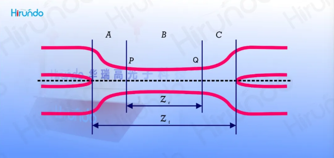
The single-fiber fusion cone area can be divided into three parts: A, B, and C, with the dividing points being P and Q. When the diameter of the optical fiber gradually decreases, the normalized cut-off frequency simultaneously decreases, and the mode field in the core gradually expands. When the normalized frequency at points P and Q is reduced to the critical value, the mode field is no longer confined to transmission within the core but is transferred to the waveguide composed of cladding and air. At this point, the role of the core can be ignored.
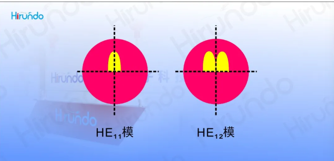
The refractive index difference between the cladding and air is much greater than that between the core and cladding, and the diameter of the B region is also larger than that of the core. Therefore, the normalized frequency of the cladding/air waveguide in the B region is much greater than that in the A region, making it a multimode waveguide. At the starting point P of area B, only the lowest-order mode HE11 is excited. After that, energy coupling will occur with other modes, with the most significant being the coupling with the adjacent mode HE12, as their propagation constants are the closest. When reaching point Q, only the HE11 mode can be recaptured by the output fiber as the core/cladding mode. The energy coupled into the HE12 mode but not yet returned to the HE11 mode will become the high-order mode in the C region and subsequent fibers and be lost.
The coupling of HE11 mode and HE12 mode in the B region is cyclic, depending on the coupling coefficient and the length of the B region. Therefore, the transmittance of the single fiber fusion cone region is related to the length of the pull cone and circulates at a certain tap length. The coupling beat length between the two modes is wavelength-dependent, so the transmittance of the single fiber fusion cone region is wavelength-dependent. The coupling between the two modes varies with the external medium. For instance, when immersed in the matching liquid to form a cladding/matching liquid waveguide instead of a cladding/air waveguide, the transmittance will also change.
Similar to the single-fiber melting cone region, the dual-fiber melting cone region can also be divided into three parts. At point P, it changes from the core/cladding mode to the cladding/air mode, and at point Q, it is recaptured into the core/cladding mode.
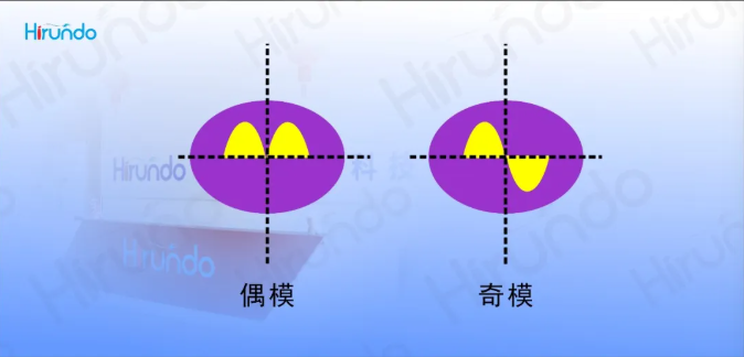
Unlike the single-fiber melting cone region, the B region of the dual-fiber melting cone region is elliptical, and the mode coupling occurs in the even mode and odd mode. The distribution of the mode field in the elliptical cross-section is shown in Figure 5.
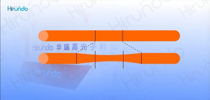
The double-fiber melting cone area can be approximated by the model shown in the above figure, where W is the width of the heating source such as the flame head (for the heating source that is swept back and forth, it can be equivalent to a certain width), and L is the stretching length on one side. It is assumed that the diameter of the cone area within the width of W is constant, and it increases exponentially on both sides. Huarui Gao can provide single-mode couplers, multi-mode couplers, full-band couplers and bias maintaining couplers, supporting steel pipe, ABS, LGX and rack-mounted packages. Various structures such as 1x2; 2x2; 2x4; "1x3; "3x3; 1x4 options are available, supporting various types of customized solutions.